-
 0086-15068518279 (Chinese)/001-5416026691 (English)
 -
 [email protected]
 -
0086-15068518279 (Chinese)/001-5416026691 (English) [email protected] 


The CNC Crankshaft Grinding Machine is a highly specialized, ultra-precision grinding center enginee...

The Follow Type CNC Crankshaft Grinding Machine represents the pinnacle of high-dynamic non-circular...


The right choice for most engine repair shops is a CNC crankshaft grinding machine with a grinding diameter range that covers your typical job mix, a...
View MoreCenterless grinding commonly causes problems such as chatter marks, workpiece out-of-roundness, surface burning, taper errors, and inconsistent part ...
View MoreCrankshaft grinders are primarily used to restore worn or damaged crankshafts in automotive engines, diesel trucks, marine vessels, locomotives, agri...
View MoreDirect Answer A grinding machine works by rotating an abrasive wheel at high speed against a workpiece to remove material through abrasion, shaping ...
View MoreCrankshaft grinding is difficult because the crank pins do not rotate around the crankshaft's main centerline, they orbit around it in a continuously shifting eccentric path, which means the grinding wheel must track a moving target rather than a fixed circular surface. A CNC Crankshaft Grinding Machine solves this with synchronized axis control that recalculates wheel position thousands of times per revolution, while also managing the deflection risk created by a long, heavy, unevenly loaded shaft. The sections below explain why this process is uniquely demanding, how the machine tracks eccentric pin journals, which crankshaft types need dedicated equipment, and how to select the right machine.
Unlike a simple shaft, a crankshaft has multiple pin journals offset from the main rotational axis by a fixed eccentric distance, one for each cylinder the engine or compressor serves. When the crankshaft rotates around its main journal centerline during grinding, each pin journal traces a circular orbit around that centerline rather than staying still. A patent describing crank pin grinding methods notes that the grinding portion of the wheel actually moves in an elliptical orbit relative to the pin during one revolution of the crankshaft, which means grinding conditions such as wheel load and contact speed change continuously throughout the cycle.
This creates several compounding challenges that do not exist in standard cylindrical grinding.
These factors are why crankshaft grinding requires purpose-built machines rather than a standard cylindrical grinder adapted for the job.
To grind a pin journal that orbits around the main centerline, a CNC crankshaft grinder coordinates two axes in real time: a C-axis that rotates the crankshaft and an X-axis that moves the grinding wheel carriage radially in and out. Academic research on crankshaft pin journal grinding, published in the peer-reviewed journal Sensors, describes this as oscillating grinding, where the crankshaft is driven by the C-axis around the center of the main journal while the pin journals rotate around that same center, and the grinding wheel performs a reciprocating chasing motion along the X-axis to follow the pin.
| Axis | Role in Pin Journal Grinding |
| C-axis | Rotates the crankshaft around the main journal centerline at a controlled, often variable speed through each revolution. |
| X-axis | Moves the grinding wheel carriage radially to follow the orbiting path of the pin journal as the crankshaft rotates. |
| Synchronization control | The CNC system continuously recalculates the required X-axis position based on the current C-axis rotation angle, following a defined motion equation. |
| Wheel rotation | The grinding wheel itself spins independently at a set surface speed to perform the material removal as it tracks the pin. |
According to the same research, the practical positioning accuracy of both the C-axis and X-axis must closely match the theoretical motion control equations for the result to be a true circular pin journal profile, since any deviation between the commanded and actual axis position introduces a contour error directly into the ground surface. This is why crankshaft grinders rely on high-resolution encoders and tightly tuned servo control rather than the simpler positioning systems found on standard OD grinders.
Not all crankshafts present the same grinding challenge, and machine specification varies significantly based on the crankshaft's size, weight, and configuration. The table below outlines common categories and their grinding considerations.
| Crankshaft Type | Grinding Consideration |
| Automotive engine crankshafts | Multiple pin journals in a compact length, requiring fast, accurate C-axis and X-axis synchronization for production volume. |
| Heavy-duty diesel and marine crankshafts | Long, high-mass shafts prone to deflection, often requiring dedicated relief or support arrangements during grinding. |
| Compressor and generator crankshafts | Frequently feature larger pin diameters and lower volume production, favoring flexible programmable machines over fixed tooling. |
| Motorcycle and small engine crankshafts | Smaller mass and shorter length, but often tighter tolerance requirements relative to part size. |
| Performance and racing crankshafts | Custom stroke and journal configurations that require flexible CNC programming rather than fixed mechanical cams. |
Heavy crankshafts present a particular engineering problem. A grinding machine patent addressing pin grinding on heavy crankshafts explains that deflection becomes a significant issue once the crankshaft exceeds a certain length and weight, and describes a relief arrangement that applies a constant counteracting force to the crankshaft during grinding specifically to manage this deflection without attaching extra parts to the shaft itself. This illustrates why heavy-duty crankshaft grinders are built with dedicated support and relief systems that automotive-scale machines typically do not need.
Deflection is one of the most common sources of error in crankshaft grinding, since the shaft is supported only at its ends or at intermediate steady rests while a grinding force is applied off-center. The following practices and machine features address this directly.
Addressing deflection is rarely a single fix. It typically requires the right combination of machine rigidity, workholding support, and a grinding sequence suited to the specific crankshaft's length and mass distribution.
Selecting a Crankshaft Grinding Machine should be based on the size, weight, and tolerance profile of the crankshafts you expect to produce, not just the largest part in your current order book. Consider the following factors.
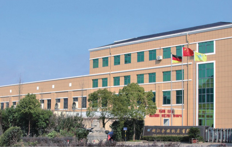
Our company manufactures precision grinding equipment from a 35,000 square meter facility with a 32,000 square meter building area, combining a dedicated machine tool production base with a hydraulic parts production base. Our product range includes ordinary and CNC cylindrical grinding machines, CNC end face cylindrical grinding machines, automatic loading and unloading CNC and end face cylindrical grinding machines, composite grinding machines, and high-precision ordinary and CNC cylindrical grinding machines. Where a customer's crankshaft or other specialized component falls outside standard catalog specifications, our engineering team also designs non-standard special grinding machines and provides supporting technology, software, training, and automation integration.
Our company holds ISO9001-2015 quality system certification and CE safety certification, and has been recognized as a National High-tech Enterprise. In 2021, we were rated as a specialized and new small and medium-sized enterprise in Zhejiang Province. With self-export qualifications in place, our products currently reach more than 20 countries including the United States, Germany, Japan, and markets across Southeast Asia, built on a long-standing commitment to quality first, reputation first, and service first.
 0086-15068518279 (Chinese)
 [email protected]
 No.100 Xueyuan Road, Jiangzao Town, Zhuji City, Zhejiang Province, China
Scan code to view mobile website
 EN
EN
 中文简体
中文简体